Introduction
Here’s another old project that I decided to redo to see if I could do better.
Back in the days when the Commodore 64 and Atari 400’s first came out, most home computers would store and retrieve data from standard audio cassette tapes. Lucky for me, my C64 had a floppy disk drive so I never had to suffer through waiting for games to load off tape, but years later I thought it would be fun to recreate this system myself. So after completing the Sony SIRC Infrared project, it seemed like I could take this firmware and make some pretty minimal changes to make it record data on tape and read data off tape.
The original project is using an Atmel ATtiny2313 with an LM2917 frequency to voltage chip to filter out the data. Looking back at this, it seems like the chip I should have used is the LM567 frequency decoder. While the LM2917 will give an output voltage based on the frequency it detects on the input, the LM567 will create a voltage or no voltage based on if a specific frequency is there or not.
While working on some W65C265SXB (6502 / 65C816) projects I started to realize the tone generator they had built into the chip that I was using to create music was probably there for an industrial purpose instead. This was the reason I decided to use the W65C265SXB board this time around.
For the original project, I used a pretty nice tape deck that I used to use to mix down music with. It was very clean / noise free and was so perfect for this. For the new project I originally tried to use a crappy Craig microcassette recorder, but it proved to be too noisy. Luckily I had an old TRS-80 CCR-81 tape recorder laying around (I should really throw this crap away.. or sell it on Ebay) that was used to record data or alternatively plain audio. This was ended up being clean enough to do this project.
The source code for this project is included in the EasySXB repository on github.
Related Projects @mikekohn.net
Videos
Here is a demonstration of some pre-recorded data being played back through the W65C265SXB onto an audio cassette being played back. The sample program simply reads from the serial port and dumps all the data to the screen (and a file). The data stored on this tape is just a 450 byte program I was using to test the serial port. https://youtu.be/daq-ugoivgc
One of my friends wanted to hear what the data sounds like, so here is a video with a closer look at the circuit and the tape player with the headphone jack disconnected so the audio goes out of the speaker. Warning: It sounds very very annoying. https://youtu.be/jL5tNkoiGzY
Pictures
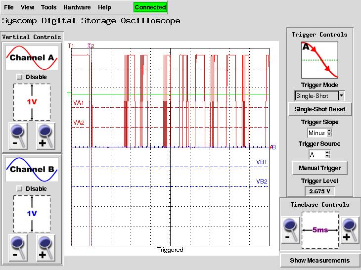
This is the letter ‘A’ being played from tape into the LM567. Kind of a dirty signal.
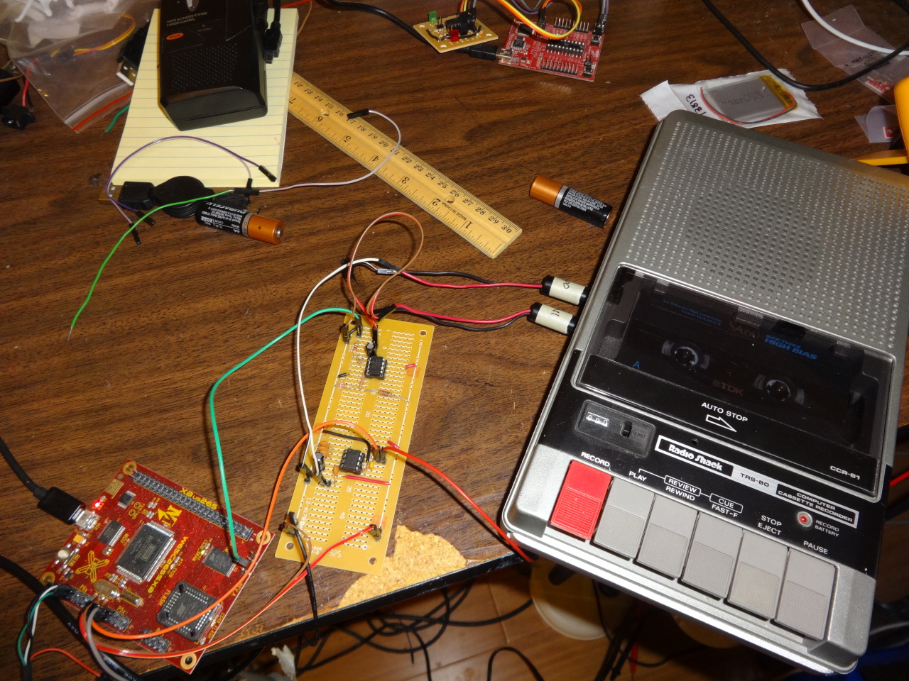
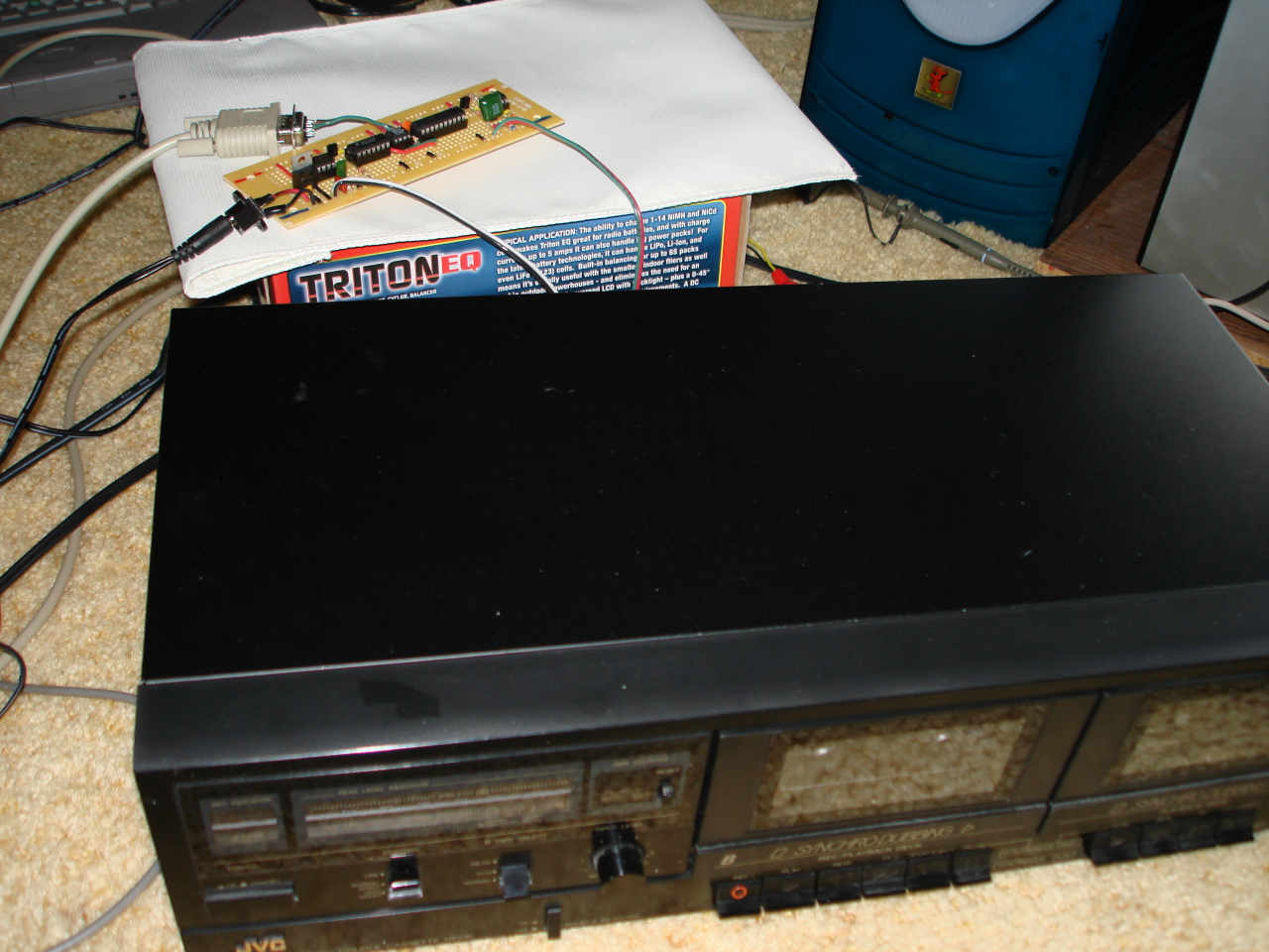
Here’s a picture of the W65C265SXB hooked up to the circuit and the TRS-80 CCR-81 tape recorder. In the far upper left is the microcassette recorder I was originally trying to use. The circuit board is connected to the tape recorder through the AUX jack for sound input and the earphone jack for sound output. There is a volume control on the side of the tape player that I set to level 2. Setting the volume to other settings caused the data to come out wrong. Kind of surprised they didn’t include and AUX out jack for hooking up to a computer.
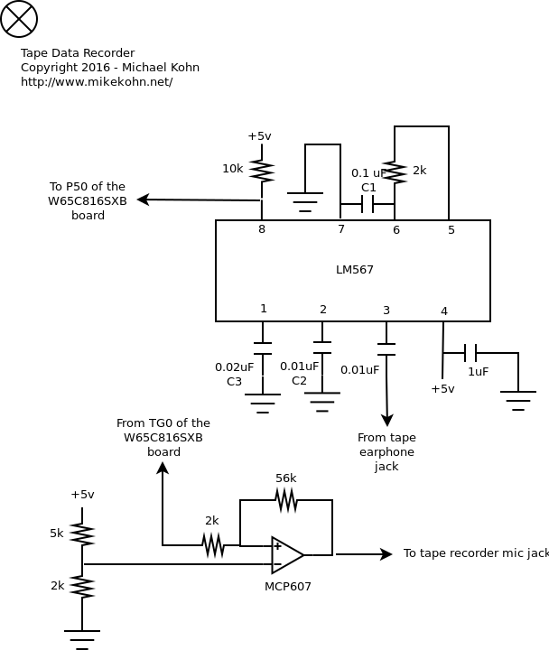
This is the newer schematic based on the W65C265SXB and the LM567.
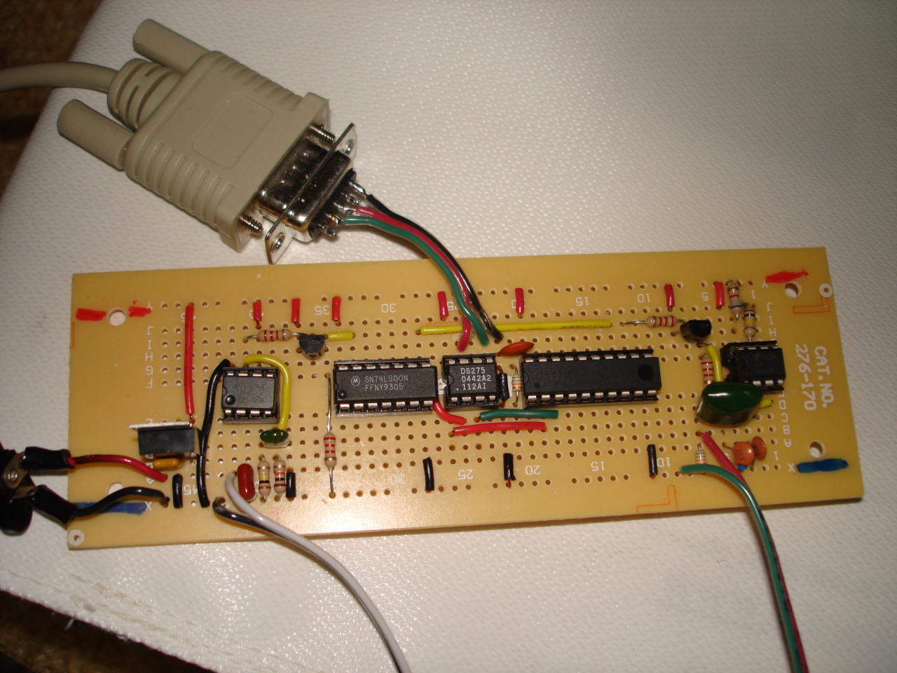
Close-up of the original LM2917 circuit.
Here is the tape player/recorder I used with the original circuit.
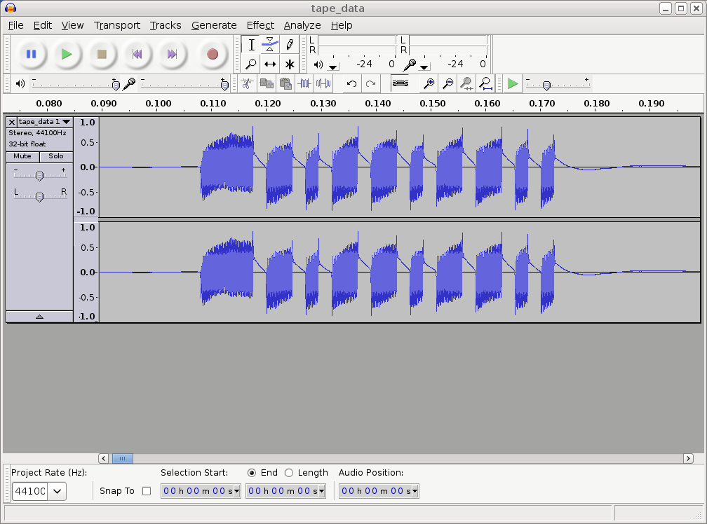
I made a recording onto tape with the circuit (just typing some stuff). I took what was on tape and recorded on the tape and played it into my computer. Here is a close-up of the first byte from the recording (the letter ‘m’). The recording is here: tape_data.mp3. Each little burst of sound is 1 byte.
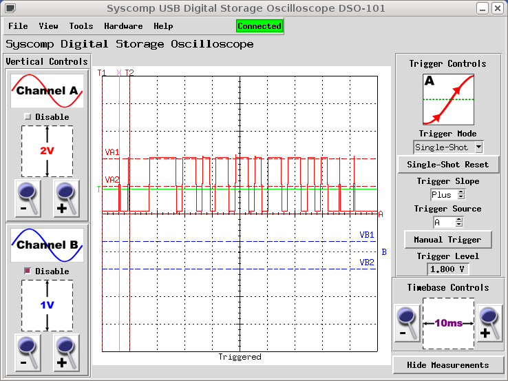
I put my oscilloscope on output of the NAND gates (which is buffering the output of the LM2917 and at the input of the microcontroller) and recorded this. It should be ‘m’ from the picture above. There are some noise spikes in here, but the firmware should ignore them.
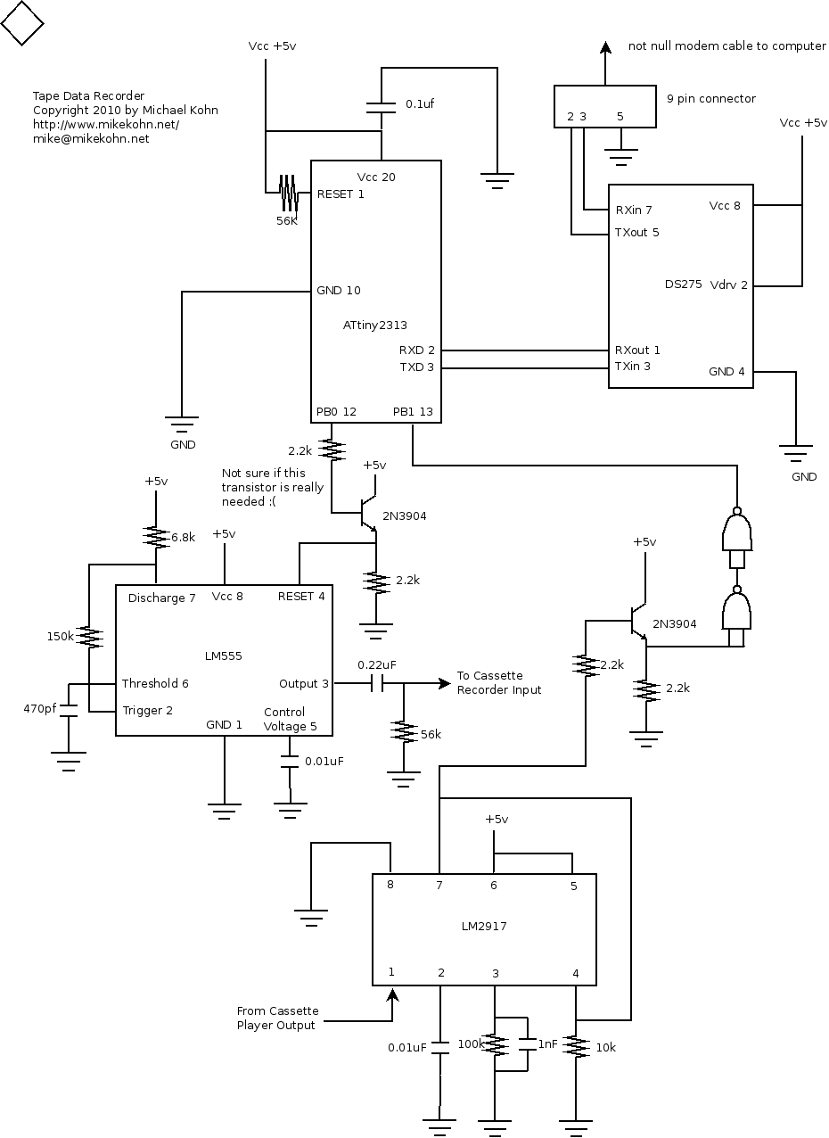
This is the original Atmel ATtiny2313 circuit with the LM2917 chip.
Explanation
To play tones on the original project, instead of using the microcontroller to create the carrier frequency I used a 555 timer chip. This was kind of a bad decision, but I had 555’s laying around that I wanted to use. For the W65C265SXB project I used the built in tone generator of the W65C265SXB. For the original project I used a carrier frequency of 10kHz, but for the new circuit I picked 4.5kHz. The reason for the lower carrier frequency is the microcassettes have a much lower frequency response (4kHz – 5kHz). Regular sized cassettes seem to be around 20kHz.
The technique to record data is to record bursts of tones where the length of the tone decides what kind of bit it is. The format for the original circuit was 7.2ms start bit, 3.6ms logical 1, 1.8ms a logical 0, and 1.8ms spaces of silence between. The data comes in Start Bit, LSb to MSb, and 1 stop bit. The new circuit is 9ms start bit, 4ms for 1, and 2ms for 0.
Because of this PWM format, the data rate and amount of data that can be recorded to tape depends on what the data is. I wrote two programs that can write and read files from tape. For the original circuit, recording a 2k GIF file it seemed to average 20 bytes per second. At this data rate one side of a 90 min tape (45 min per side) can hold about 52.7k. Not bad if this was 1970 :).
I used 2 NAND gates to buffer the output of the LM2917 and turn a 4v output to a logical 0v or 5v (so it’s equivalent to the IR receiver in functionality). The NAND gate wouldn’t react to the output of the LM2917 directly so I put a transistor in between. Looking back at this, this seemed like another weird decision.
Source code
git clone https://github.com/Mortis69/EasySXB.git
tape_data_recorder-2010-02-06.tar.gz