Step 1: Plug in your W65C265SXB via USB
The W65C265SXB is powered by 5V DC. There are no onboard regulators. It is recommended to use a Micro USB cable powered from either your PC or a 5V wall adapter. This will both power the board and provide a WDCTools development interface (when connected to a PC). The SXB has a built-in simple operating system called a Monitor. The Monitor is always there and is the built-in interface that is all you need to get started with the WDCTools and your first project.
All of the SXBs have built-in 32K bytes of SRAM for program and data storage and a socket for 128K bytes of FLASH memory organized as 32K byte blocks for easy switching between applications, tasks, or saving precious data. Unlike the Apple, Commodore, and Atari systems, no floppy or hard drive is needed. You are free to use the low power solid-state memory in ways you only might have dreamed of before.
The memory contained in these small boards is equal to or greater than the memory of some of your favorite legacy systems that used the 6502 microprocessor.
-Micro USB Cable and Micro USB OTG adapter M/F NOT included
Step 2: Get Started with WDCTools and Terminal Interface
-
Download WDCTools Install WDCTools and set update preferences with installer. If you have email or other issues downloading the tools, click here (you will need to unzip before installing).
-
Download the WDC Programming Manual
-
Find WDCTools Support videos on YouTube
The WDCTools is NOT for resale or reverse engineering of our technology in any form and is NOT provided for the development of commercial products that use non–WDC 65xx processors in Core or Chip form.
The W65C265SXB both has a monitor ROM that on reset will communicate to a terminal using a UART on the W65C265S. You can use programs such as HyperTerm (PC), HyperSerialPort (PC), PuTTY (MAC, Linux, PC), ZTERM (MAC), XTERM (MAC, Linux) to communicate with the boards. Or if its a more mobile interface you seek, with any Android device you can use the FTDI UART Terminal!
But what if you wanted to customize your interface to your SXB? We thought it would be interesting to have a simple script to interface with the board. Why not Python? Python is straight forward and easy to use. Check out the WDC GitHub Page for a starter script that will work with the W65C265SXB. Feel free to make it your own. You can even add functions to the board and interact through the terminal (turn on/off lights, read sensors, etc). Let us know what you come up with!
You should be up and running with your board and tools. Please see the W65C265XB product page for technical information, Datasheets and more. Next, we will run a small demo program.
Step 3: Browse to your WDCTools example project
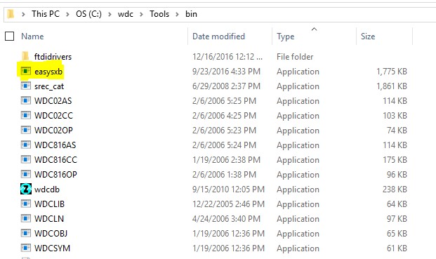
All of the executable for WDCTools can be found in the C:\wdc\Tools\bin directory. One of the many useful tools that you can find there is a Serial Terminal application created by Joe Davisson. He has allowed us to include EasySXB with our installs of WDCTools. You will find the 64-bit Windows version in the “bin” directory. Joe has the latest source on Github and the latest downloads at SourceForge.
We will get started with the W65C265SXB using a simple program to work with the P72 LED that is on the board.
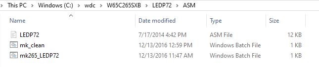
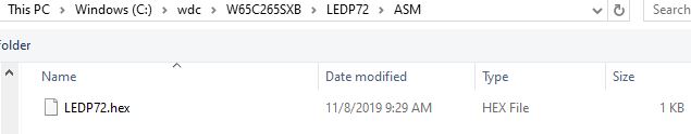
The project file is located at C:\WDC\W65C265SXB\LEDP72\ASM\. This project has a batch file that will assemble and link the project. It will also launch EasySXB.
Double click on the mk265_LEDP72.bat file to execute the batch file.
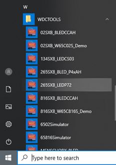
Another method to run the BATch file is to select it from the Start Menu.
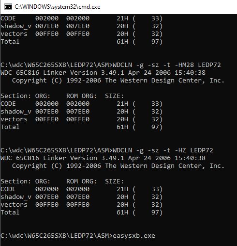
Once the batch file runs, a windows Command window appears. It will stay on the screen until you close it. It should be the same as below if everything ran correctly.
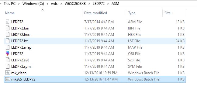
Back in your Windows Explorer window, you will see several new files were created. These include the .OBJ (Object) file that is used by the linker to make the .BIN (WDC Binary Format output), .HEX (Intel HEX Format Output), and .S28 (Motorola S-Record 28 Format output) files. EasySXB uses the .HEX file to load into the memory of the W65C265SXB. A listing file (.LST) file is also created. You can view that file in any text editor and see both your code and the corresponding assembled addresses, opcodes, etc.
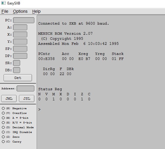
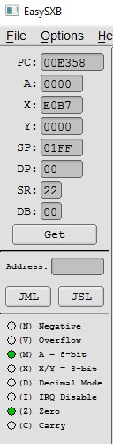
The last window that opened is EasySXB. This is the Serial Terminal program that we use with the W65C134SXB, W65C265SXB and the MENSCH™. EasySXB has three Menu Options (File, Options, and Help). Below the Menu bar, the application has 4 Import sections. The first is the Registers section (located in the upper left corner). The values of each register are displayed after the “GET” button is pushed. A terminal connection must be established before you can “GET” the register values.
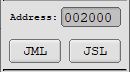
Just the register section is the “JUMP” section. You must input an address that your program is located in for the project. For the W65C265SXB you must include the Bank Address followed by a colon, and then the address in HEX format. Ie. 00:0200 will be for address $0200 in bank $00.
The next section is the status register. Each part of the status register is indicated here. A green light means that the corresponding register flag is set HIGH (“1”). No light indicated the flag is not set (“0”). These values are also indicated by the “SR” value in the Register section.
To the right of all the previous sections is the Terminal Window. This is where all communication between the W65C265SXB and EasySXB will be displayed.

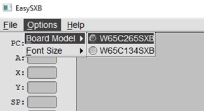
Before we can communicate, we must make sure we have the proper settings in EasySXB. For the W65C265SXB, make sure that in the Option-Board Model menu, “W65C265SXB” is selected.
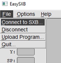
We are ready to connect our Micro USB cable into both the USB port on our PC and the other end into the J6 USB connector of the W65C265SXB. Now, “Connect to SXB” from the File Menu.
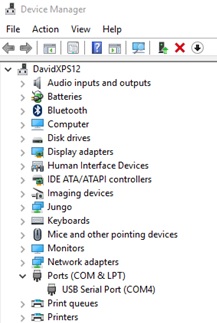
A prompt will appear asking for you a port to connect to. This is the COM port that the device was assigned by Windows. You can find this by opening your Windows Device Manager. You will be looking for the “Ports (COM & LPT)” section as below. Type the number found after “COM” in the EasySXB prompt and press Connect.
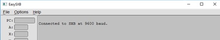
There is now text in the Terminal Window section of EasySXB.
Now that EasySXB is connected to the W65C265SXB, we can now communicate from the board to EasySXB. Press the “S1” RESB pushbutton switch on the W65C265SXB. This is the master reset button for the board.
Upon reset, the W65C265SXB will transmit a welcome message from Serial Port 3 of the W65C265S chip. This welcome message can be seen below. Along with the welcome message, the W65C265SXB will send the current values for all of the registers and detailed Status Register flags. You can press the “GET” button in the Register section to see the register values appear there.
On reset, these values will be the same as what was sent with the welcome message.
Now we can upload a simple program. Click on “File”, then “Upload Program”. The Upload Program dialog box opens. Choose the HEX file that was created by the BAT file, then click the Open button.
The terminal will display that the program is uploaded correctly.
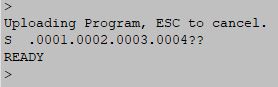
Type the starting location of your code. For the P72 program, it is at $00:2000 (do not type the $, the “:” is optional ). Now click on the JML (JuMp Long) or JSL (Jump to Subroutine Long). Both will work for this example.
You will notice that the EasySXB terminal display will update as follows:
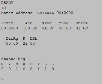
The P72 light on the W65C265SXB has changed as well. For extra practice, you can edit line 251 (lda #$00) to lda #$04 to turn the light off. You will need to run the batch file again and load the new hex file using the steps above.
This is just a simple example and you can explore the various pin functions and features of the W65C265S chip.