Welcome to the Getting Started Guide for the Simulator. The Simulator is part of the WDCDB.exe tool within the WDCTools. For this guide, we will focus on working with the W65C02S microprocessor and W65C22S VIA within a software simulation environment and not with any specific board. This is a great start to exploring 65xx technology. These simple steps will guide you through connecting your board to your computer and running your first program. Please see the Simulator/Debugger (WDCDB) User Guide for more details of the features of the Simulator.
Step 1: Download and Install WDCTools
-
Download WDCTools Install WDCTools and set update preferences with the installer
-
WDC Programming Manual – This is a fantastic programming reference for 65xx microprocessors.
The WDCTools is NOT for resale or reverse engineering of our technology in any form and is NOT provided for the development of commercial products that use non–WDC 65xx processors in Core or Chip form without a license.
Step 2: Work through an included Simulator example project
We will explore the Simulator using a simple program to work with the 8 LEDs that are on the board. The project file is located at C:\wdc\65C02Simulator\8LED_CCAH\ASM. This project has a batch file that will assemble and link the project. It will then launch WDCDB.exe. The WDCDB.ini has an option to switch between the software simulator and hardware debugger and is currently set for simulation.
There are two ways to launch the project:
1.) Double click on the mk265_QBX8LEDS.bat file to execute the batch file.
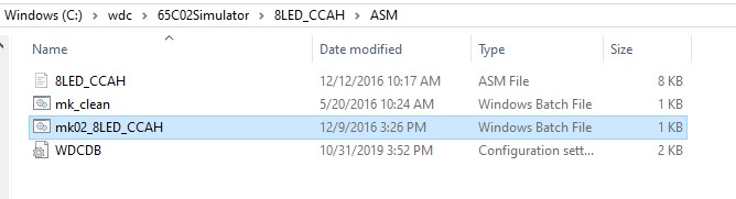
Files contained in the code example.
2.) Click on the Start Menu option for “6502Simulator” under the WDCTools Start Menu folder. This was created when you install WDCTools.
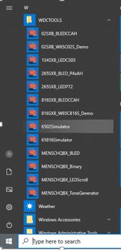
Start Menu icon for 6502Simulator project.
Choose the method that works best for you. Once the batch file is run, a windows Command window appears. It will stay on the screen until you close it. It should be the same as below if everything ran correctly.
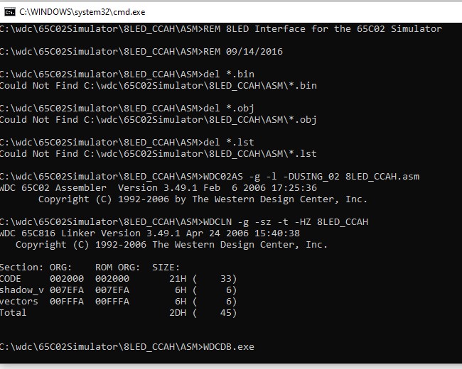
Command prompt output after BATch file runs.
Back in your Windows Explorer window, you will see several new files were created. These include the .OBJ (Object) file that is used by the linker to make the .BIN (WDC Binary Format output). A listing file (.LST) file is also created. You can view that file in any text editor and see both your code and the corresponding assembled addresses, opcodes, etc.
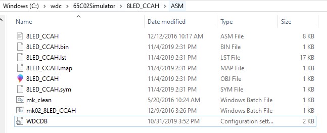
Windows Explorer shows files after BAT file is run.
The last command ran is to open the WDCDB.exe Simulator window. Below is a screenshot of the configuration of the Simulator. This is just an example of how you can set up your windows. There is a window that shows the representation of 8 LEDs and the values of the W65C22S (VIA) registers. The “Status” windows letting know where data is loaded, etc. The “Registers” windows show the current values within each of the W65C02S microprocessor registers. The “File” window displays the code used for the program. It also highlights the line of code that is located at the current location of the microprocessors program counter (upon loading, the program will start at $2000). For this example, we have two “Data” windows open. One is showing data at $2000 and the other at $3000. The data at $2000 is the program that we wrote. The data window at $3000 is where the user can change those values directly in the window and as the program is stepped through, the values will be read from those memory locations and written to the W65C22S Output Data Register B, which is connected to the 8 LEDs within the Simulator.
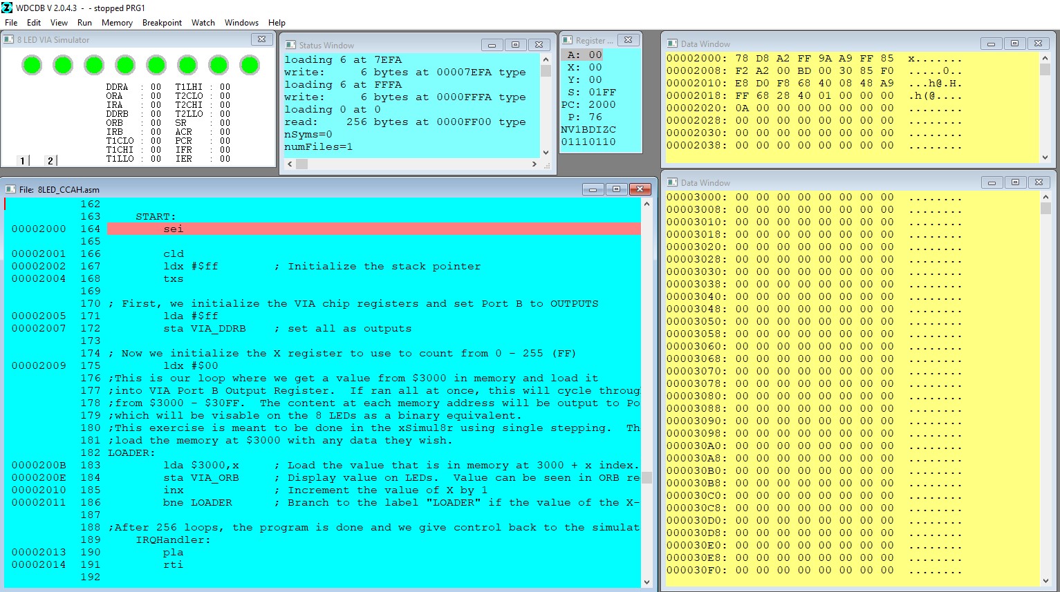
Simulator window on startup.
Now that we are familiar with the windows within the Simulator, let’s use it to run our example. We will start by looking at the code for the example. Note that a semicolon before the text is seen as a comment in the assembler.
;Example code to control 8 LEDs driven from the W65C22 VIA Port B
            org   $2000       ;Our program code will be at $2000
      START:
            sei
            cld
            ldx   #$ff        ; Initialize the stack pointer
            txs
The “org” statement tells the Linker tool that the next instructions will be linked at $2000. The next 4 instructions are important instructions that you can use in almost any of your programs to start. The SEI (Set Interrupt Disable Flag) instruction does just as it says; it will set the Interrupt Disable Flag to a “1” which will disable interrupts on the microprocessor. We do not need to use any interrupts for this simple example. The CLD (Clear Decimal Mode Flag) instruction shifts the processor back into binary mode from decimal mode. Note that in the Register window you can see the status of these flags. The Simulator has he Decimal Mode Flag cleared and Interrupt Disable Flag set by default, but this is just a good habit to handle these flags when you are working with the hardware. The next two instructions are used to setup the Stack for the processor. This will ensure that the process is ready to run program instructions and will not get lost. LDX immediate will load the X Register with the value declared which is 0xFF (FF in hexadecimal). TXS will transfer the value of the X Register onto the stack.
Let’s now single-step through these first 4 instructions. Press the “F7” key on your keyboard, or select the “Step Into” option from the Run menu in the simulator as shown.
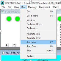
Click on “Run” –> “Step Into”
Each time you press “Step Into” or “F7” you will single-step through the program. The Program Counter (PC) of the microprocessor will increment for each instruction. SEI, CLD, and TXS are single-byte instructions, and LDX immediate is a 2 byte instruction. Step through each of the first four instructions. Afterward, the Program Counter will be at $2005. The Registers should be as shown below:
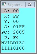
Register Window
The next two instructions will be used to interface to the W65C22S.
; First, we initialize the VIA chip registers and set Port B to OUTPUTS
            lda   #$ff
            sta   VIA_DDRB    ; set all as outputs
LDA #$ff – Load the Accumulator with the value declared which is 0xFF. STA VIA_DDRB will store the 0xFF to the memory location that is assigned to the label VIA_DDRB. We can use labels to name memory locations that we will use often. VIA_DDRB stands for VIA (Versatile Interface Adapter, nickname of the W65C22S), Data Direction Register B. This is one of the 16 registers within the W65C22S. It is an 8 bit register that is used to set the Data Register for Port B to either Inputs or Output. Each bit of the register corresponds with a wire on the Data Port. Writing a 0 to a bit make that Data line an INPUT, while writing a 1 to the bit makes that Data line an OUTPUT. 0xFF in hex is the same as “11111111” in binary, so we are writing a 1 to each bit in the Data Direction register. That makes each line of the Data Register Port B as an OUTPUT. We are doing this because those Output Data Register lines are hooked up to the 8 LEDs in the simulator. If we use Step Into again twice to single-step through these instructions, we should see the LEDs turn off and the DDRB has “FF” (all outputs) and ORB has “00”.
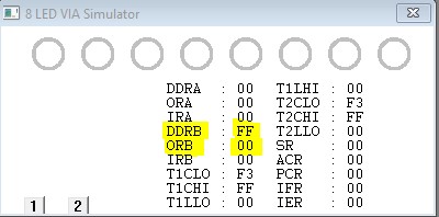
Data Direction Register B value is updated in the window.
Now that our Port B is set to outputs, we will next start writing values to the Port B output register to different values so that the LEDs will change.
; Now we initialize the X register to use to count from 0 – 255 (FF)
            ldx #$00
LOADER:
            lda $3000,x       ; Load the value that is in memory at 3000 + x ; index.
            sta VIA_ORB       ; Display value on LEDs.  Value can be
                              ; seen in ORB register of VIA
            inx               ; Increment the value of X by 1
            bne LOADER        ; Branch to the label "LOADER" if the value of
                              ; the X-register is not $00
These 5 instructions create a simple loop that reads a value from memory starting at $3000 (up to $30FF) and writing that value to the Output Data Register Port B. The first instruction will only be run once since the BNE (Branch if Not Equal) will branch back to the “LOADER” label. The LDX #$00 initializes the X Register to 0x00 so that we can use the X as an index register for the LDA instruction. LDA $3000,x is the LoaD the Accumulator instruction, using the X register as an index. The first time we run this instruction, X is 0x00 so we are loading the accumulator with the value that is in memory at location $3000. The next instruction is STA VIA_ORB. We are storing the value that is now in the accumulator to the location of the label VIA_ORB. VIA_ORB is the Data Register Port B that is hooked up to the LEDs in the Simulator, so the corresponding LEDs will change. Any bit or the ORB with a 1 will drive the matching LED. The next instruction is INX or INcrement X. This instruction will increase the X register value by 1. This is used to move the index we use for loading the values from memory. We use BNE to Branch if the Z (zero flag) is not set. Since we did an increment of the X register, the Z flag is “0”. The BNE instruction will branch back up to LOADER each time until the X register is incremented from FF to 00. At that point, the Z flag will be set and the processor will go to the next instruction after the BNE.
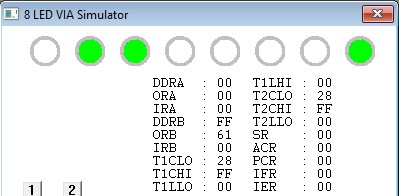
The Data window currently shows 00 (hexadecimal) for all of the data in that page. Click on the first set of “00” at 3000 and change the values. As you type, you will see the values change. The Data window has a nice feature where you can type an ASCII character to the right side of the hex values. As you type a character at the 8 dots to the right of the hex values, the hex values will change for the appropriate ASCII character. See below for examples of values you can type into the Data window.
Data Window showing the updated contents at memory location $3000 and up.
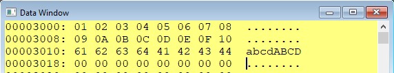
Now that we have values in the Data window at $3000, we can single step through our loop. Remember that every time you run the “STA VIA_ORB”, the LEDs should change to the proper value (in binary) that is in the accumulator. This example is good to practice for converting numbers between decimal, hexadecimal, binary, and ASCII. Based on the Data at the $3000 page, the first value to be stored to the ORB is $01 hex (“00000001” binary). The furthest right LED should be the only LED that is lit.
LEDs showing “00000001” in binary.
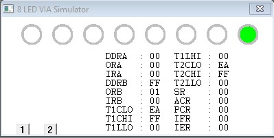
Once you get to the ASCII “a”, you will hex “61” in the ORB register and the LEDs will correspond to “01100001” which is the binary equivalent of 0x61.
LEDs showing “01100001” in binary.
That is all the program does. You can keep single-stepping through the program, changing Data to read new values, etc.
We hope you have learned more about our Simulator and possibly the W65C02S microprocessor and W65C22S VIA.