Quick Reference:
-
If you have never used the W65C02SXB before, please work through the
W65C02SXB Getting Started Guide first.
-
Download 02EDU Getting Started Project (unzip into C:/wdc/W65C02SXB folder)
0.) W65C02SXB Getting Started Guide
If you have both the EDU and SXB boards but have never worked with the W65C02SXB, please work through the W65C02SXB Getting Started Guide before proceeding.
1.) Plug your W65C02EDU onto your W65C02SXB
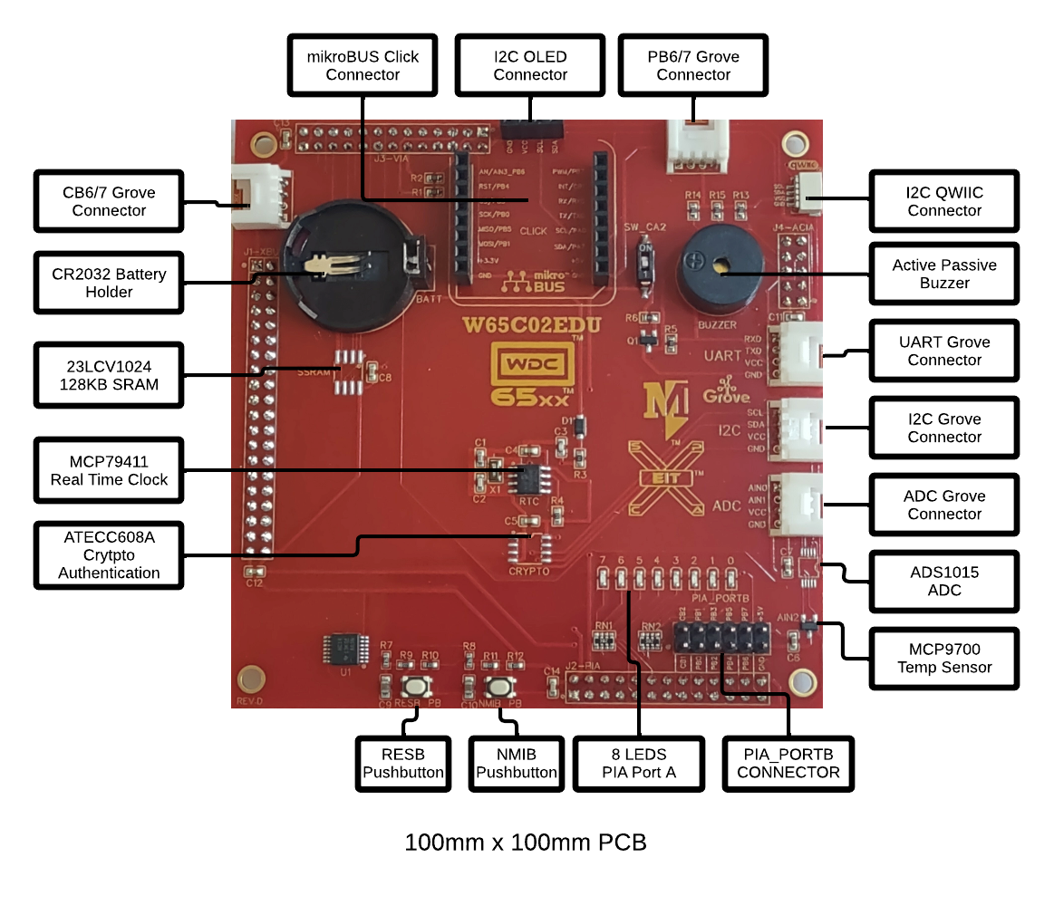
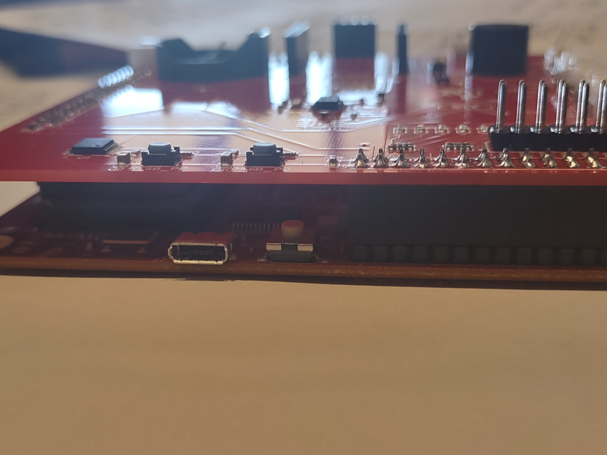
The EDU board is an add-on board for the SXB, therefore it does not work by itself. Therefore we must connect the two first. The J1-J4 connectors on the EDU board are female sockets. These headers will fit directly onto the J1-J4 pin header connectors of the SXB board. Align each connector and gently press down. This is best done on a solid surface. Be careful with the PIA_PORTB connector as those pin headers are sharp. Alternating pressure at all 4 corners of the EDU will help it wiggle onto the SXB. You may find it easier to start the J4 ACIA connector and then work clockwise to the J2-PIA connector, etc. Be careful to make sure all of the pins are straight and nothing is bent during the process. Once you have a secure connection, you are ready to upload your first demo program. NOTE: once the EDU is secured it will be very difficult to remove.
2.) Example Program
If you did not download the Getting Started Example above, please do so from here. Extract/unzip the .ZIP file into the C:\WDC\W65C02SXB folder. Next, we will get started with the W65C02EDU using a simple program to work with the 8 LED and the buzzer on the EDU board.
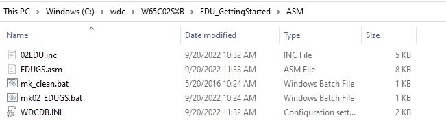
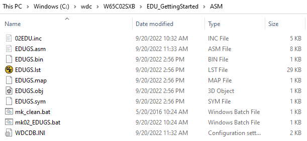
The project files can be seen using Windows Explorer in the following folder: C:\WDC\W65C02SXB\EDU_GettingStarted\ASM\.
This project has a batch file that will assemble and link the project. It will also launch WDCDB Debugger.
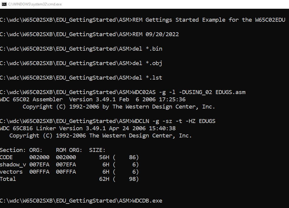
Double-click on the mk02_EDUGS.bat file to execute the batch file.
Once the batch file runs, a windows Command window appears. It will stay on the screen until you close it. It should be the same as below if everything ran correctly.
Back in your Windows Explorer window, you will see several new files were created. These include the .OBJ (Object) file that is used by the linker to make the .BIN (WDC Binary) file. The debugger uses the BIN file to load the program into the memory of the W65C02SXB. A listing file (.LST) file is also created. You can view that file in any text editor and see both your code and the corresponding assembled addresses, opcodes, etc.
Another window that opens is the USB Options dialog box. This is very important for downloading programs into any WDC board using the WDCDB Debugger. If you do not have any other USB serial devices attached to your computer, you will only see one listing for your SXB board. Click on the name of the device, then click the Okay button.

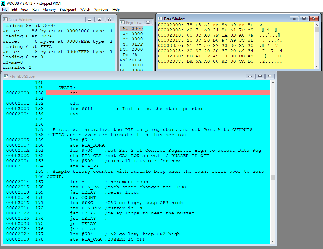
The WDCDB Simulator/Debugger will launch. Below is a screenshot of the configuration of the Debugger for our program. This is just an example of how you can set up your windows. The “Status” windows let you know where data is loaded, etc. The “Registers” windows show the current values within each of the W65C02S microprocessor registers. The “File” window displays the code used for the program. It also highlights the line of code that is located at the current location of the microprocessors program counter (upon loading, the program will start at $2000). We have one “Data” window open showing data at $2000. The data at $2000 is the program that we wrote. If the file window is not showing like below, there may have been a communication issue with the board. Hit the RESB (RESB_PB) Pushbutton on the EDU board to restart the board and then rerun the batch file.
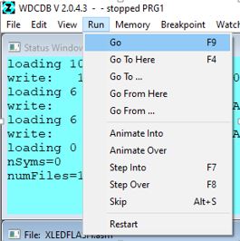
Now that the board has the program uploaded to it, we are ready to run the program. To do so, click on the Run menu, then click on Go. You can also hit the F9 function key on your keyboard. To stop the board while it is running, press the NMIB pushbutton, which is just to the right of the RESB pushbutton.
Here is a short video showing the LEDs changing quickly as the counter increments. This is an example of an 8-bit binary counter. When the counter gets to 0xFF (all 8 bits are a 1), the counter will then reset to 0x00 on the next increment. When this happens, the example code sets the PIA CA2 signal HIGH to turn on the buzzer. After a short delay, CA2 is brought back LOW and the buzzer stops. Within the WDCDB debugger, you can step through the code (and over the delays) to see the LEDS change slower. You can also play with the code to add more delay loops or even make your own delay loop.
This is just a simple example and you can explore the various pin functions and features of the W65C02S, W65C21, W65C22, and W65C51N chips as well as the onboard RTC, and any Grove, QWIIC or MikroBUS modules that interest you.